Wireless Charging of devices

Wednesday, 7 October 2015
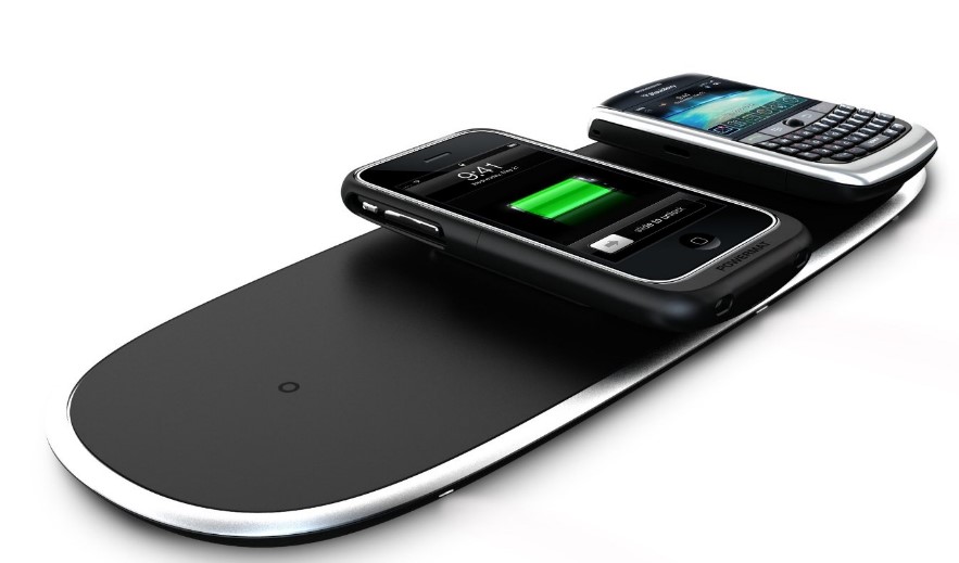
Now a days, we heard of wireless charging of mobiles through power mats. The basic concept of wireless charging is in faraday's law, the law states that whenever a conductor is placed in time changing electric field an emf(Electro motive force) called as voltage is induced in that particular conductor. This concept is used and is applied to wireless charging of devices.

Whenever a mobile is placed in power mats, this power mats are capable of emitting alternating current which will create a magnetic field and mobile is equipped with conductor(wireless charging contacts), and now according to the law, this magnetic field will induce the voltage in the conductor and the mobile gets charged

.


Only power mat need to be plugged in. With this concept, with one plug and one cord we can charge many devices by placing on power mat.
Read more ...

SUPER CONDUCTORS-EXPLAINED

Tuesday, 6 January 2015
        Now we will learn about new concept called 'SuperConductors'.We will start from beginning,metals are classified into 3 types conductors,semiconductors and insulators.when voltage is applied to conductors or semiconductors,electron flow(current) occurs, and this flow is restricted by resistance which is the property of conductors.This resistance is resulted due to impurities,defects and vibrations of materials in the crystal lattice.This phenomena is called resistivity which depends upon length and area of the conductor.

        Inverse of resistivity is conductivity.conductivity of conductor lot depends on temperature.Normal conductors conduct below 30k.Scientists worked a lot to increase the conductivity of a conductor.They have varied the temperature but couldn't get much from conductors,because the conductors already have free electrons and increase in temperature will further add energy to this free electrons which makes them to move in less organised patterns making less conductivity at higher temperature.This is not the case with semiconductors,when temperature is increased,the energy is added and in turn helps to free a electron,so at high temperatures more electrons are freed which increases the conductivity.This kind of transition from normal conductivity to super conductivity which will occur when we go from room temperature to high temperature is called Superconducting state and the metals are called Super conductors.The phenomena of exactly zero electrical resistance occurring in certain metals when they are at high temperature is called Superconductivity.

What causes superconductivity?
        We had seen that certain metals suddenly become superconductors,when they are kept at critically high temperature.Reason is, at this temperature electrons inside them will join with each other which are called copper pairs.At this temperature electrons will move more freely without being scattered.High temperature will result more free electrons thus increasing the conductivity of semiconductors at high temperature.At present scientists are working hard to have this feature at room temperature.

        Another interesting thing that need to pay attention with superconductors is Meissner Effect.Normally materials allow magnetic fields to flow through them,but when semiconductors were at high temperature,they increasingly expel these fields.This effect is called Meissner effect and the principle is used in maglev trains.

        Technological applications of superconductors are adopted in Maglev trains,MRI(Magnetic Resonance Imaging) and NMR(Nuclear Magnetic Resonance) as they require strong electromagnetic fields. 
Read more ...

New Technologies in the Market

Sunday, 26 October 2014
1.Ocean currents: New source of renewable energy


                Ocean currents, a source of energy that is gonna add up to the list of renewable energy sources in the years to come. Turbines placed beneath the ocean are able  to rotate with the help of forces acting upon them, such as breaking waves, winds, tides caused by gravitational pull of sun and moon. These spirals developing beneath are able to generate mechanical energy that makes turbines to rotate, which cuts the magnetic flux. According to Faraday law, whenever a conductor is placed in the region of time changing magnetic field an EMF is induced into the conductor. This results in current in conductor which is valuable.

2. Erascan: New white board scanner and eraser

                Erascan is able to scan all the writings and drawings on the white board and is capable of storing the data in digital format. It lets you to transfer the data over mail, share it or delete it. It is able to identify, who is written on board and stores emails, urls, images etc in digital format. The idea is to keep the copy of drawings for future use.

3.Drones: New way of delivering products

                Biggest e-commerce website has recently announced that It may deliver products within 30 min or less to make customer delight. Drones are devices which can fly in air and carry the products. These are controlled by people. Since these involve in security of country we should wait for clearance of government.
                The idea had been extended by Facebook founder i.e with the help of drones it is easier to provide internet services to rural areas and to increase its users. No longer one can depend upon optical fiber to meet the increasing demands. Now these drones will be revolving at a certain height and will provide the internet services to every user.

4.Cybernetic Reading :New way of reading books for blind people

                Implanted devices are fixed at our forefinger and at ear as shown in figure. When one touches the printed words with this devices, the words are pronounced at ear, with which one can read without actually seeing. These implanted devises are able to recognize the characters and is able to relay the information at ear. It’s a good gift for blind people apart from Braille.
Read more ...

Brain Computer Interface-The Next Generation User Interface

Tuesday, 6 May 2014
Brain-computer interface (BCI) is a fast-growing emergent technology, in which researchers aim to build a direct channel between the human brain and the computer.
These are linguistic independent and can be used anywhere across the world .


Types of BCI:
1.    Invasive 2. Non-Invasive 3. Semi Invasive
Invasive: Invasive BCIs are implanted directly into the grey matter of the brain during neurosurgery. As they rest in the grey matter, invasive devices produce the highest quality signals but are prone to scare tissues.
Non-Invasive: In this process the user wears a wearable cap which is studded with electrodes.It has no complication of surgery but signals are weak as they are placed above the thick skull.
Semi Invasive: Semi-Invasive BCI devices are implanted inside the skull but rest outside the brain rather than amidst the grey matter.
Applications:
• Provide disabled people with communication, movement restoration.
• Provide enhanced control of devices such as wheel chairs, vehicles, or assistance robots for people with disabilities.
• Provide additional channel of control in computer games.
• Monitor attention in long-distance drivers or aircraft pilots, send out alert and warning for aircraft pilots.
• Develop intelligent relaxation devices.
• Control robots that function in dangerous or inhospitable situations (e.g., underwater or in extreme heat or cold).

• Bionics/Cybernetics
• Dream Capture
• “Google Search” through brain

BCI research is an interdisciplinary endeavour involving neuroscience,engineering,signal processing,rehabilitation and lies at the intersection of emerging technologies such as Machine learning and artificial intelligence among others.
BCI is considered as a new frontier in science and technology.
Read more ...

GIGABIT FIDELITY(Gi-Fi)

Wednesday, 23 April 2014

         Gi-Fi will helps to push wireless communications to faster drive. For many years cables ruled the world. Since the installation of these optical fibers need much cost,caused a greater difficulty  and thus led to wireless access. The first and foremost one is Bluetooth which is used to cover 9-10 meters. Later on WI-FI entered into field which can cover 91 meters. However the need for increase in data rates are growing, so to meet the requirements we need another way of transmission.
Gi-Fi is a wireless technology developed to work in a range of 10m with transmission rates of gigabits per second. Gi-Fi is evolved since in Bluetooth and WIFI transfer rates are 800kbps and 11mbps respectively, but for Gi-Fi as the name specifies it is gigabits per second.

How it works???
            In  this we use duplexer so that antenna  can be used for both transmission and reception purposes. During transmission, intended data files are converted from IF signals into RF signals using two mixers. To have  high signal strength  the converted RF signals are fed to power amplifier at the transmission side. During reception, RF files are converted to  a range of  normal data files. In receiver side, we use heterodyne  receiver construction  to avoid leakage from direct conversion.    


         With Gi-Fi we can even reduce the power consumption from 10Watts(in Bluetooth and Wi-Fi) to 2Watts which is mainly essential. With the GIFI we can access home appliances and internet radio modules.  Gi-Fi is even highly secured as it follows IEEE 802.15.3C By considering the success of Wi-Fi and Wimax. we can surely say that GIFI is able to play a key role in next years.
Read more ...

latest land mine detection technology

Saturday, 12 April 2014
Detecting land mines is the major problem in combing areas where terrorists place land mines to kill the public as well as soldiers in reaching them. There are many technologies developed so far, but here we talk about latest one to detect the land mines before stepping on it. This technology is under design by LEMUR STUDIO design organization located at Columbia. This technology needs two devices, one fitted on shoes for prior detection and another on hand to view the exact location of land mine through GPS. 
The key elements in the two devices are coil, microprocessor, radio transmitter, hand held device, GPS. Coil in the shoe is to emit the electromagnetic waves, microprocessor is used to detect the changes in the electromagnetic waves, radio transmitter is used to send the changes to the hand held device and the GPS is for locating the object in terms of longitude, latitude and elevation.
HOW IT WORKS???
The coil in the shoe is emitting electromagnetic waves(these are released when electrons pass through conductor) continuously, when these get disturbed by the land mine, the signals at that moment are captured by the microprocessor which are sent to hand held device through GPS. The alarm present in the hand held device gets on and position of the land mine can be detected before stepping on it.

Read more ...

Neurocam that records automatically what interest us

Wednesday, 19 February 2014
 In 20th century it takes so much of time to take photo with a normal camera as we have to open the shutter and then click on the button. In this span of time the incident may disappear. So to overcome this problem a latest technological device called Neurocam has been introduced.

Neurocam system includes a headband equipped to hold an iphone next to the wearer’s temple. The phone is fitted with a special prism so that the camera can record footage from the wearer’s point of view. The headset also includes EEG sensors that can scan your brain for correlative spikes in interest. The Neurocam iphone application assigns the EEG data a value from 0 to 100.                            
                                          

                                         Fig: Electroencephalography reading
Neurocam uses brain wave sensorslike as in the moving cat ears and TV navigation, but this time hooks up with your smart phone camera. This prototype, demoned at last week at Japan’s Human sensing 2013 conference gauges your interest on a scale of 0 to 100 and if your brain wave redout tops 60, it will start to record video, eventually transforming the footage into five second GIFs. In order to get the iphone camera to eye-view, the smartphone connects to a headband which houses the brainwave sensor. Sideways on the camera sensor then faces through a prism so its looking at what you are looking at…and not just inside of your ear.
                                                      

                                                       Fig: Neurocam system
                                                    

                                                     Fig: wearing of Neurocam system
The experimental wearable, barring the smartphone hanging off, looks pretty similar to other brain wave reading wearables, although the addition of an I phone will certainly make it weighter in comparision. The neurocam is the latest product to come from the neurowear project, which already gave us the aforementioned Nekomimi cat ears. We are not sure how comfortable we’d feel having all those radio waves near to our need for an extended period, although according to Digi info news, this device, including its current design and shape are still in the throes of development for now. The world always needs more GIFs.
                                                            It may look like poor man’s Google glass, but don’t let the iphone strapped to the side of your head thing fool you, neurocam and its accompanying app may foretell the future of advertising.
                                                         

                                                                 Fig: Necomimi cat ears


                                                          Fig: screen of iphone while recording
                                                            Before the introduction of this Neurocam the status of a person is recognized based on the different types of waves produced by the brain. For every type of wave produced by the brain the mood of a person is stated. But now based on the frequency range of the brain waves the meter reading of the neurocam varies.       
                                                       
                                                  
                                                                 Fig: Different types of brain waves
                                                            Because this system is hands free, we think it could capture a life log, which would be different from deliberately pressing a shutter to capture things you like. As an application in a B2B environment Neurocam could determine what goods in stores interest people. And because the information includes position data, you can do mapping, so it could also show what places people are interested in as an aid for urban development planning. We think it could be used in lots of ways like that.
                                                            The algorithm for quantifying brain waves was co-developed by Associate professor Yasue Mitsukura at Keio University.
                                                            It is probably not a good idea to wear the camera during speed dating or shopping though you’d probably end up with way to many unnecessary GIFs. Not to mention you will look ridiculous.

Read more ...

EVO MOUSE

Sunday, 9 February 2014
Hi friends, let us now look in to new technology regarding evolution of mouse. Mouse was firstly invented in 1960 by Douglas Englebart  to interact with computer screen which is made of wood and has two perpendicular wheels which are used to track the movements and to translate into motion along one axis. The first mouse model has a cord attached to rear part of device which was looking like a tail which resembles the common mouse.
Later on mechanical type of mouse was invented which is also called ball type mouse, replaced the external wheels which were there in first mouse. The ball has two wheels embedded in it; the rotation of each wheel is translated in motion along one axis. But it was hard to operate as ball moves only on flat surfaces and on some mouse pads only.
To overcome the wheel structure an alternate mouse was developed and is called optical mouse, which has optical source like LED , on movement of light the cursor used to find the path on computer screen.  Since LED is noncoherent (not in particular direction) the power used by device is more and the mouse is unable to operate on opaque surfaces.
Laser type of mouse is developed which emits light in particular direction which make mouse to use less power consumption and even laser is operable on opaque surfaces. Later on gyroscopic mouse was introduced which allows user to access the mouse in air. Since then nothing has been changed.

Now CELLUON company introducing EVO mouse a dog shaped device which sits at one side and gives access the user to use any surface close to like touch pad. No hand held device in hand. User no more have to carry the mouse and move it in order to move the pointer on the screen. Now you have to do is to move the finger on the surface and the pointer will move accordingly.
                                    
HOW IT WORKS?
When the EVO mouse is connected via USB or Bluetooth, two lights emit from the device which tracks your finger and enables you to perform your task just like an ordinary mouse.
EVO mouse is developed with Electronic perception technology which is single chip imaging technology the enables electronics components to form a 3D map of their surroundings. With this virtual keyboard is possible which make user to feel the keyboard in front of them and work on. A system is embedded in it which will detect which key is pressed.
FUNCTIONALITIES:
As I said before EVO mouse converts the flat surface into a touch pad. It allows the usual mouse functions and beyond to it. On the surface in front of device if we
Tap once=single click
Double tapping =double click
One finger holding and next finger tapping=right click
Double tapping and dragging=scroll
We can even perform rotate, zoom, forward, backward, and by using our finger we can write and draw.
EVO mouse is convenient to use and setup and it works with all PC’s. It is truly evolution of mouse.

Read more ...

Difference between Normal diode and LASER,LED Diode's

Friday, 24 January 2014
 Hi friends, every one who knows about electronics devices will be familiar with diode and optical sources like LASER and LED. The optical sources are also diodes. By knowing this every one may think that why a normal diode could not emit light where as a LASER and LED does?
The answer to this question lies in developing of these normal and optical diodes.
The major differences between normal and LASER and LED type of diodes is
“Semiconductor materials used for making”
Due to this we have variation in formation of junction between P and N region and differences in band gap energies also plays a role to not emit light(radiate) in case of normal diode
*As we know that Normal diode is made from semiconductor materials of group 4 like Si and Ge. These are doped with either group 3 or group 5 elements to form  P and N type materials respectively and when this doping is done on single semiconductor material, a diode is formed.
*In this case we will see a non heterojunction formed between P and N regions of a diode, this is called depletion layer(or)region  which is increased or decreased  by biasing.
*We have used single semiconductor material for making, so indirect band gap exists between conduction and valence band. On baising  electrons  and holes recombine across the band gap and third particle generated in this process will conserve the momentum which is the reason for normal diode to not emit the light.
 *LASER and LED diode cant be developed with single semiconductor element, as these need direct band gap materials. These are made from compounds of a group 3(Al,Ga,In) and group 5(P,As,Sb). These are suitable for developing optical sources like LASER and LED.
*In case of laser and led diodes hetrojunction is formed between two adjoining materials with different band gap energies.
*In direct band gap semiconductor, electrons and holes can recombine directly across the band gap without needing a third particle to conserve momentum. In this radiative recombination is sufficiently high to produce an adequate level of optical emission.
Why Si and Ge are widely used as semiconductor materials?
It is known that inert gases like Ne(10),Ar(18),Kr(36) contain stable electronic configuration. These atoms have no tendency to combine with other atoms as they have stable electronic configuration. Elements like fluorine(9) and chlorine(17) are very reactive as they are one short of stable electronic configuration. Electronic configuration is defined as systematic arrangement of electrons in the atomic orbits. The maximum number of electrons present in each orbit is generally given by 2(n*n),where n=number of orbit.
1st orbit =2,2nd orbit=8,3rd orbit=18….Electrons present in the last orbit of an atom is called "valence electrons".
Si,Ge belong to group 4 of periodic table and they have 4 valence electrons at T>0k,neither have  stable electronic configuration nor they are too far to attain stable electronic configuration like nonmetals. This is reason why group 4 is treated as semiconductor metals. In this we also have carbon which is non metal so we will not consider it, remaining are Sn,Pb,Fl which are post transistion metals (poor metals) and these have lower melting and boiling points which make them to not consider as semiconductor metals. So Si and Ge are widely used as semiconductor metals.
Read more ...

Introduction to RADAR Systems.

Saturday, 18 January 2014

RADAR is abbreviated as Radio detection and ranging. Radar is an electromagnetic system, which generates EM signals to detect and to find the distance from system to objects (or) targets near to it.
How it can detect?
As said earlier radar transmits the EM signal from an antenna, these signals spread out in space and when they hit any object they come back to receiver, present in the same antenna. Returned signal is called ECHO signal and the direction it came from provides the direction of object with respect to radar system.
How it determines the Range (distance)?
Radar system is capable of determining the distance from system to object. we know that distance(R) = speed(c) * time(t).
R=(CTr)/2--->eq.1; where c=velocity of signal
                             Tr=pulse repetition time period.
In the denominator 2 is placed, as we calculated the time for to and fro motion.
This range equation does not provide the correct distance from system to object, so many factors have to be included like radar cross section, aperture gain, gain of antenna(G), the power transmitted from the antenna(Pt),minimum power detectable signal(Smin),by this radar equation is developed.Even this is not perfect.
Many other factors like noise need to be included,as noise is the chief facor limiting receiver sensitivity,it needs to be described.Even if you operate in noise free region,then also noise is entered which is due to thermal motion of conduction electrons in the ohmic portions of reciever,this is called johnson noise or thermal noise.So the total noise power at the output of receiver is equal to thermal noise power multiplied by noise figure(Fn).The minimum power Smin will become as
Smin=KToBnFn(So/No),replacing in the above equation will give you the better range valve.

*If a signal is transmitted from radar,it may strike the object at multiple locations, due to this many pulses are usually returned from a object on each scan and can be used to improve detection.The process of summing  all the radar echo pulses to improve the detection is called integration of radar pulses.The integration activity can be performed before the second detector(in the radar block diagram) and after the second detector.The integration performed before is called predetection or coherent detection and after is called postdetection or noncoherent detection.Predetection is mostly  adopted as it is capable of storing the phase information for further purpose like finding the range in CW radar,but postdetection is not entertained as it destroys the phase informaion for further access.
The integration effeciancy is Ei(n)=((S/N)1/n(S/N)n)
                             Where n=no of pulses integrated
                                      (S/N)1 =signal to noise ratio of a single pulse required to produce given probability of detection(n=1)
(S/N)1 =signal to noise ratio per  pulse required to produce same  probability of detection when n pulses are integrated.
Placing the above one in the radar equation we get better results.

*The transmitted power Pt in the radar equation is called peak power.This is not the instantaneous power of a radar wave.The average radar power Pav is ratio of average transmitter power over pulse repetition period.
                                      Pav=(Ptt/Tp)           Tp=pulse repetition period
Replacing the above one in radar equation will give better results.
                             
*Even in the final equation,we havent considered the losses take place in the system,these reduce the signal to noise ratio at the receiver output.These losses are classified depending upon whether they are predictable or not.The losses that are predictable are antenna beam shape losses,plumbing losses,collapsing losses and the losses that aren't predictable are operator losses,integration of radar pulses,the losses due to field degradation.
Plumbing losses are the losses that are experienced in the transmission.
Antenna beam shape losses include the pulses that are returned from target are received correctly or not by aperture of receiver antenna.
Collapsing losses occur in radar that is capable of integrating additional noises samples along with the wanted signal,the additional noise results in a degradation.
*Now we look on another type of radar called CW radar.The difference between the CW radar and the pulse type of radar what we have discussed is,suppose if strong signal has to be separated from weak echo(normally 10-18 times that of transmitted power) then it is better to use continuous wave rather than pulse wave as carrier.
Upto now we had considered that the object(target) is in rest.Now if the target is in motion then relative velocity exists between radar and the target,an apparent shift in frequency will result,this is doppler effect and is basis of CW radar.the doppler frequency is given by
                             Fd=2VrF0/c ------->eq.2         where c=velocity of light
                                                                   Vr=relative velocity
                                                                   F0=Transmitted frequency.
So the frequency that is received at the receiver will be F0 +(or)- Fd.
When the object is approaching towards radar system we have F0+Fd and when the object is moving away from radar system then we have F0-Fd.By this we will know Fd as we know F0(transmitted frequency), and if it is placed in the above equation(eq.2),we get the relative velocity(Vr) existed between radar system and target.
*The major disadvantage with the CW radar is that it cannot measure the range,this can be overcome by modulating the CW carrier.The inability of simple CW radar to measure is related to the relatively narrow spectrum of its transmitted waveform and a widely used technique to broaden the spectrum of CW radar is to frequency modulate the carrier.This type of radar is called FMCW(frequency modulated continuous wave) radar.
In this type of radar the transmitter frequency is changed as a function of time in a known manner which is transmitted and echo is received after time T=2R/c(from eq.1).This echo signal frequency,along with transmitter signal frequency is fed to mixer and the output is beat frequency Fb. suppose if there is no doppler frequency shift i.e no relative motion existed between radar and target,the beat frequency is equal to range frequency Fr=(df0/dt)*T
                                                                   Fr=2Fm*(2R/c)----->eq.3 
We know the returned frequency at the receiver Fr,modulating frequency Fm,velocity of light c,placing all these we get the Range(R).
We calculated the range when the target is in rest,for suppose if target is in motion,then we get two Fb(up)=Fr+Fd
                                                                                                     Fb(down)=Fr-Fd   
Above two equations are added to get the Fr,which is placed in the above equation(eq.3) to get the range(R).       
If suppose multiple frequencies are resulted from the target,then narrow band pass filters are used at the receiver to separate individual frequencies.
*Now we look on another type of radar called “MTI(moving target indicator) radar”,major differences between CW and MTI radar is CW radar operates with continuous wave and the MTI radar operates with pulse wave,so MTI radar is also called as pulse doppler radar.The principle remains the same but there is slight differences between MTI and pulse radar.MTI radar operates with ambiguous doppler measurements but with inambiguous range measurements,whereas the pulse doppler radar operates exactly opposite.
The moving targets produce,with time ,a “butterfly” effect on the A-scope,but for the display on the PPI(plane position indicator),we need delay line canceller,which acts as a filter to eliminate the dc component of fixed targets and to pass as components of moving targets.
*Another type of radar we have to know is “Tracking radar” which measures the coordinates of target and provides data about the position of target in future.
Appliations of Radar:
We have many applications of radar as it can see through those conditions impervious to normal human,such as darkness,dnow,fog and rain.
In ATC(Air Traffic Control),radar is employed for purpose of safely controlling air traffic en route and in the vicinity of airports.
In Aircraft navigation to avoid terror attacks.
In ship safety also radar is employed.In titanic movie the ship hit the iceberg and collapsed because the human was visualising as the human eye cannot see through snow he couldn’t inform it before.now in the ships radar is employed to  signal the operator before he founds it.
In space also radar is employed to detect the asteriods and smash it when found it is approaching towards earth.
In military also radar is employed to detect the enemy moves.
In highways police use it to detect the speed of the vehicles.
In sports like cricket it is used to measure the cricket ball speed.

There are many,these are only few.                 
Read more ...

SMART CARD-EXPLAINED

Thursday, 5 December 2013
In simple words smart card is a credit card with a microprocessor.
*This is the microprocessor that is embedded in smart card. Vcc is power supply,Rst is used to reset the card communication,clk is used to provide card with a clock signal,Vpp is programming voltage,Gnd is to provide ground,I/O is serial interface as smart card uses it and C4,C8 are AUX1,AUX2 respectively and are used for USB interfaces.
*Before knowing more about smart cards let us have a look on credit cards as these smart cards are evolved to overcome the disadvantages in credit cards.
*Credit cards store information on magnetic strip line, which is easily breakable. Magnetic strip technology remains in wide use in US, however the data on stripe can easily be read, write or even can modified as stripe is not the best place to store information, we need an alternative and confidential place to store it.
*To protect the customer business in US, smart cards are introduced which will overcome the above said disadvantage.
*Smart card usually contain an embedded microprocessor, which is under gold plated contact pads and performs mathematical encryption calculations used in security function and also store additional card holder account data.
*In Europe, health insurance and banking industries use smart card extensively.
*A smart card has 8kb of RAM,346kb of ROM,256 kb of PROM and a 16 bit microprocessor
*Smart card uses a serial interface and receive power from external sources like card reader.
How it works?
*When a smart card is inserted in smartcard holder, transaction is similar to that of an ATM, but in here power goes from smart card reader(machine) to chip and switches it ON, once it is ON, it is able to conduct, an electron conversation  with chip reader. When the reader is online, the chip uses the reader to communicate to card issuer,during this time security procedure is activated that authenticates the card. A fake card would not be able to duplicate the security procedures and would be detected invalid.
*Magnetic strip information on credit card can be copied and put on fake card,  which looks exactly as valid card. The technology required to copy data  from smart card to a fake card is beyond capability of criminals, and the information sent online to authenticate the card is different for every transaction ,also to attempt to physically remove the chip from smart card would cause the chip to blow and chip cannot be used again.
*Smart card is of two types
1.       Contact smart card:
Contact area of smart card is approx. 1 sqcm,comprising of several gold plated contact pads, these pads provide electrical connectivity when inserted into reader, which is used as communication between smartcard and host(PC),these do not have batteries, power is supplied by card reader
2.       Contactless smart card
In this type of smartcard, card communication with Is powered by reader through RF induction.
Problems in using smart card:
1.The plastic card in which chip is embedded is fully flexible, so hard to maintain it.
2.As I said before, smart card is inserted into smart card holder, if the holder contains malware then it tries to know the information which makes the card  to turn invalid.
Read more ...

Working of WI-VI(WIRELESS VISION)

Saturday, 23 November 2013
Hi friends,this time came up with new technology "WI-VI(Wireless Vision)".This technology uses  "WI-FI"(Wireless Fidilety) to allow user to look into the walls.This technology analyses the reflected WI-FI signals to estimate an object in a particular room,even if it is in motion we can able to detect the exact location of object.
Here in this case,the user has two antennas which generate WI-FI signals continuously with 180 degree phase difference and a single receiver.Generally a portion of WI-FI signal can penetrate in to wall.When two antennas radiate,due to 180 degree change in phase they cancel out each other without reaching at receiver when they hit any stationary objects,but when these signals hit any moving object there generates a change which will appear at the receiver,by analyzing the received signal we estimate perfect location of object.
Actually this concept is similar to RADAR(Radio detection and ranging),in which 'radio' signals are transmitted in to space to 'detect' the presence of object and 'ranging' involves knowing the exact location of object from the system,how?range or distance is speed over time,we know the speed of transmitting signal and the time taken for signal to strike the object from system(user),by this range is detected.
WI-VI systems are capable of tracking the person in a closed room.Assume that a WI-VI device is fixed outside the room,initially room is empty,when a person enters into it based on the movement of person the device is capable of showing variations i.e when he moves towards the WI-VI, signal may be in one format and when he moves away from it we can see the signal in another format.A small variations can also be grabbed by WI-VI device.

Read more ...

Introduction to Zener diode

Monday, 11 November 2013
Hi friends,this time we wanna discuss about zener diode which is heavily doped diode and is specially fabricated to with stand high power dissipation.
Main application of zener diode is, it can act as a voltage regulator.
Forward characteristics of zener diode:
when high potential is applied at anode compared to cathode,then the characteristics of 
zener diode are
Negative characteristics of zener diode:
when lower potential is applied at anode compared to cathode,then the characteristics of 
zener diode are
Major concern related to zener diode is determining the state in which the zener diode is residing,there are various steps that to be followed in this process,
  1. Replace zener diode by an open circuit
  2. Find terminal voltage across the diode from N to P side,say vt
  3. If vt>vz,  zener is reverse ON  and replace it with vz
  4. If vt<vz,  zener is OFF and hence open circuit.
Consider a circuit ,
now the circuit becomes 
Terminal voltage Vt=(8*1.2)/(1+1.2)=4.3v and since Vt<Vz zener is OFF hence open circuit.
If  RL=3.6k then terminal voltage Vt=(8*3.6)/(1+3.6)=6.26v. Here Vt>Vz hence zener is reverse ON and replace zener diode with Vz=6v.
Now the question is how to place a terminal voltage,the answer is conventional direction of zener voltage is considered to be opposite to the direction of normal PN diode,because  PN diode is used in forward biased and zener diode is used in reverse biased.
For RL=3.6,the circuit becomes 
Read more ...

TRANSISTOR Disadvantages-MOSFET Advantages

Thursday, 31 October 2013
Hi friends,this time i wanna talk about basic electronic devices, they are transistor and mosfet with their disadvantages and advantages respectively. Major disadvantages that i would consider for transistor are,
1.Input impedence
2.Stability
I would also explain how these two are advantages for mosfet.
1.Input impedence : 
For transistor:Any small input at the base terminal will turn transistor active and make it work (i.e as a amplifier or as a switch),which is not required at particular small input. Transistor should respond only to a reasonable input .This indicates the input impedence(Ri) of a transistor is low.Actually for CC based transistor configuration,the input impendence is upto 500k ohms,which is enough, but if transistor is biased then due to R1 and R2 the net input impedence will decrease(R1||R2||Ri).
For mosfet:Mosfet abbreviates metal oxide semiconductor field effect transistor,as the name itself indicates presence of oxide(SiO2) an insulator,which  prevents mosfet not to respond for small inputs
2.Stabilty
For transistor:We desire a fixed operating point that to in active region with Ib,Ic,Vce.The flow of small current(due to low input impedence) into BJT results in dissipation of electrical energy inform of heat.This results in rise of tempoerature which inturn increases Ic0 but Ic=(alpha)IE+Ic0,so Ic also increases.With this operating point is disturbed.It is referred as bias instability.To overcome bias instability,we have bias circuits which will stabilise the Q pont even change occured in Ic0 and temparature.Ic0 increases by 2 times for every 10 degree rise in temperature.
For mosfet:Bais instability is occured in BJT due to low input impedence,but as i said mosfet has high input impedence(due to SiO2) compared to transistor,so chances of instability is less in case of mosfet.
Read more ...

Circuit which indicates the charging level of battery

Saturday, 19 October 2013
Hi friends ,As the need for rechargeable devices are increasing it is necessary to maintain the life of electronic devices which runs with  battery.Life of any rechargeable device depends upon the usage of charging capacity it has.Overcharging leads to reduce the life of device.Now a days due to overcharging many of the devices are out of work field.So if we know proper charging level of battery at every instant of time,it would help us to know whether to charge the battery or to use it.My circuit provides this features i.e when the battery is fully charged we can see a LED light glowing by this one will come to know that the battery is fully charged and has to unplug it.If not it need to be charged. Today i wanna show a circuit which will indicates the charging level of a DC storage battery.


Circuit description:
Input is an alternating voltage signal of 220v and 50hz supply,given to capacitor which is used to block DC,Stepdown transformer to reduce the signal level ,a rectifier to convert AC to DC,inverting and non inverting amplifiers,LED,1 v DC source and the battery whose charging level is to be detected.
Working:
Initially AC signal is passed through 'C' to block DC,which is fed to step down transformer to reduce the voltage signal from 220v to 13v.Now this is given to rectifier circuit for conversion process i.e from AC to DC.This constant 13V is given to non inverting terminal of opamp-1,inverting terminal is given with battery positive terminal for same opamp.Output of opamp-1 is given to inverting terminal of opamp-2 and its non inverting terminal is grounded.Output of opamp-2 is fed to LED which has -1v supply.
Operation:
case:1 Assume initially the battery has 2v in it ,V+>V-,therefore V01 is 13-2=11v,V02=-11v,since the potential at anode is much less than potential at cathode the LED doesnot glow.It means that battery is not yet fully charged.
case:2 Assume now the battery is fully charged i.e upto 13v,V+=V-,therefore V01=0,V02=0 and now the potential at anode(0v) is greater than potential at cathode(-1v),LED glows and indicates us that battery is fully charged and need to be unplugged.
*Since the ouput of rectifer is given to battery,it charges the battery when it is discharged by the user.
*Here two opamp are used,but the same work can be done with single opamp.For better explanation i has shown two.
,

Read more ...

WIRELESS ELECTRICITY-EXPLAINED

Thursday, 3 October 2013
Movement of electrons (current) in free space without using any proper conduction path between two electronic devices is referred to as wireless electricity.Long before it is a dream but after a few years it will come true.
  • Everyone knew that conductor has free valence electrons, by applying proper voltage (nothing but force) these electrons move and results current(flow of electrons).

1.Actually the concept of wireless electricity has started with faraday's law.
It states that whenever a conductor is placed in magnetic field(time changing) an induced emf(electro motive force) or voltage is induced in another conductor.This is considered as base for wireless electricity. Without any proper conduction path,this induced emf will results to move electrons in another conductor.This concept resulted to discover transformer.With the transformer we are able to alter voltage from a high valve(received from station)to a value required for home appliances.This is beginning for wireless electricity.
2.Second thing I would consider is from the basics of antenna. Actually antenna is an interface between free space and transmission line that converts V/I waves into E/H waves at the transmitter and viceversa at the receiver.HOW? When a voltage(V/I) is fed at the input, due to electric field(electrons) and magnetic field(as these electrons are moving),E/H waves are released into medium, this conversion V/I into E/H process is called radiation and at the receiver E/H is converted back  to its V/I form, this process is called induction.
By adopting both radiation and induction techniques we can transmit electricity without proper conduction path between two devices.
Conclusion:From first technique we need a strong magnetic field between two wireless devices and from second technique we need an antenna for wireless transfer of electricity.
Read more ...

Software's for Win 7 homebasic and Add-on for chrome

Saturday, 28 September 2013
Hi friends this time i would like to share two softwares for windows 7 home basic operating system and a Add-on for Chrome browser.
1.Software-"personalization -setupfile"
Every user of win 7 home basic will not find personalize option in the popup menu,but where as in win 7 professional , ultimate and home premium, users can have it with which one can change the wallpaper of desktop by one click.To get the personalize option for home basic ,download a setupfile "personalization" and get installed in your PC.And now you can see personalization option in popup menu.But we have still left out with "next background option",by which wallpaper changes automatically.
2.Screen Shot Add-on-"CLIPULAR"
    For chrome users,Clipular is one of the best screen shot Add-on.When Clipular is added to chrome,one can take screen shot for the tabs s/he has been working on.Screen shots of full screen or else a part can be taken which will be stored in book(Add-on book),for usage of that image(screen shot) one has to login ,save the file and use it.Since it is add-on for chrome one cannot use it outside chrome.Shortcuts are specified ,which ease its usage.
3. Software-"EPICPEN"
    Those who want to draw on screen, to specify a matter to another user. Epicpen software is useful.By using this,one can able to highlight the matter,that s/he is going to convey.By installing this software one can use a pencil,eraser and color selection.But one cannot draw straight lines or a particular shape,only zigzag lines are allowed.The file can be found at http://sourceforge.net/projects/epicpen/
Read more ...